What are the New Updates of Fusion 360?
What’s New?
Sketching and Modeling
- New Sketch Chamfer
- Go to Sketch environment >Modify>Chamfer
Here in the new update of Fusion 360, now user will get the benefit of using three chamfer tool.
i.e. 1. Equal Distance Chamfer, 2. Distance and Angle Chamfer, 3. Two Distance Chamfer.
Chamfer tool feature option will appear in Sketch mode and this will make user to switch to different chamfer tool.
Learn more about how to use chamfer tool in details
Add an equal distance chamfer
- On the Sketch contextual tab, select Modify > Chamfer > Equal Distance Chamfer .
- Pause the cursor over the first line or a vertex.
If you pause over a vertex, a preview of the chamfer displays.
- Click to select the line or vertex.
- If you selected a line, pause the cursor over the second line to see a preview of the chamfer.
- Click to select the second line.
- Drag the distance manipulator handle in the canvas or specify a distance value.
To end the command, press Enter.
The chamfer geometry and distance dimensions display in the canvas. The second distance dimension is driven by the first distance dimension. If you update the first dimension, the second dimension will update as well, so that the two distances remain equal.
Add a distance and angle chamfer
- On the Sketchcontextual tab, select Modify > Chamfer > Distance And Angle Chamfer .
- Pause the cursor over the first line or a vertex.
If you pause over a vertex, a preview of the chamfer displays.
- Click to select the line or vertex.
- If you selected a line, pause the cursor over the second line to see a preview of the chamfer.
- Click to select the second line.
- Drag the distance manipulator handle in the canvas or specify a distance value.
- Drag the angle manipulator handle in the canvas or specify an angle value.
- To end the command, press Enter.
The chamfer geometry, distance dimension, and angle dimension display in the canvas.
Add a two distance chamfer
- On the Sketchcontextual tab, select Modify > Chamfer > Two Distance Chamfer .
- Pause the cursor over the first line or a vertex.
If you pause over a vertex, a preview of the chamfer displays.
- Click to select the line or vertex.
- If you selected a line, pause the cursor over the second line to see a preview of the chamfer.
- Click to select the second line.
- Drag the first distance manipulator handle in the canvas or specify the first distance value.
The first time you move one of the distance manipulator handles, both distance values adjust.
- Drag the second distance manipulator handle in the canvas or specify the second distance value.
- To end the command, press Enter.
The chamfer geometry and distance dimensions display in the canvas. Each distance dimension is independent. If you update the first dimension, the second dimension remains as you set it, and vice versa.
Exploring Design Avatars and Design Reservation in Fusion 360
Fusion 360 has improved way teams can collaborate in distributed design workflow. When working on Assembly modeling design team often distribute work among multiple designers.
The proximity of designers working in a distributed design can lead to conflict because it’s difficult to see who is working/accessing a design at given time. To reduce the conflict fusion 360 has introduce Design Reservation, Avatars, and Reservation Badges.
These changes make it easier for teams to work concurrently in an assembly giving designers the visibility on what design they are working and who is working with details. These working environment helps Fusion 360 users work in team collaborate and flexible design process.
Avatars in Fusion 360
The avatars have been enhanced to be more visual and responsive and now appear in the data panel, browser, and active document tab when multiple people are accessing a design. Projects requiring multiple designers typically begin with a discussion about who will be responsible for different areas of a design. When a design is opened, it is immediately apparent other collaborators have parts of this design open, and everyone knows who is in the vicinity before making changes.
Design Reservation in Fusion 360
A Reservation Badge is a white dot applied to the lower-right corner of a project member’s Avatar while they’re editing a design. The Reservation Badge indicates that the project member has made a savable change to the design. The design is reserved by that project member until they save or discard their changes.
The avatars and reservation badges provide designers with instant access to valuable information. In the image above, collaborator RC has the build plate open but has not made changes, while collaborators GG and CS include the Reservation Badge indicating reserved status. This badge tells others that active editing is happening and that they can expect changes in those designs.
Find out more about our softwares and services on our latest blog page!

Autodesk Docs Features and Latest Guidelines
AUTODESK DOCS
Autodesk Docs is a cloud-based common data environment that provides document management and control to the entire project team. With Autodesk Docs, AEC teams can simplify collaboration and data management across design to construction and streamline document review and approval workflows.
AUTODESK DOCS FEATURES
-
Design-to-construction connection
-
Document Collaboration Communicate with markups and issues, enhancing collaboration between teams.
-
Full set of markup tools
-
track and resolve quality issues across teams from a single centralized issue list
- Attach documents as references to RFIs, Meetings, Forms, and Assets to improve collaboration and reduce miscommunication
-
Support for 2D & 3D Designs
- Open, save, move, rename, and delete files directly from your desktop with Desktop Connector
ADDING AUTODESK DOCS FOR SINGLE USER AND MULTI USER AEC COLLECTION
Multi-user AEC Collection subscriptions were included in that migration in the form of a single-user standalone subscription of Autodesk Docs for those customers.
The standalone subscription was fulfilled via an automated process for this group (to be completed by 4/30/21). Multi-user AEC Collection subscriptions are still being sold via Deal Review Board (DRB), exception for add seats and net new. Renewals of multi-user AEC Collection will be allowed until August of 2022.
Autodesk is giving Autodesk Docs to customers who have AEC Collection subscriptions. For single-user customers, this was done systematically using an automated subscription process linked to the single-user AEC Collection itself.
With respect to multi-user AEC Collection customers, Autodesk is giving a standalone single-user subscription for Docs.
LATEST GUIDELINES FOR DOCS SUBSCRIPTION
- The use of the Autodesk Docs subscription is only valid in the context of providing a matching subscription to the customer’s existing multi-user AEC Collection subscription.
- Zero-dollar Docs and multi-user AEC Collection should be in the same order where possible.
- Docs subscription should match the multi-user AEC Collection seat subscription 1 for 1.
- If a customer trades in their multi-user AEC Collection license for a single-user license, the standalone single-user subscription of Docs is no longer valid since the Docs seats will be provided as part of the single-user AEC Collection.
- The standalone Docs subscription provided with the multi-user AEC Collection will be co-termed to the multi-user AEC Collection subscription end date.
- If you have already renewed the multi-user AEC Collection prior to receiving access to the SKUs below, a separate order for just the Docs renewal can be submitted.
- The zero-dollar Autodesk Docs SKUs should only be used after the customer has received the original standalone Docs subscription through the automated RPA process.
For contract managers of single user subscriptions of the AEC Collection, Autodesk Docs will show up as a product under the AEC Collection. For contract managers of multi-user subscriptions of the AEC Collection, Autodesk Docs will show up as a separate line item in Autodesk Account.
Find out more about Autodesk Softwares on our blog page!

What’s New in Revit 2021 for Structural Engineers?
Steel Detailing Service:
The bulk of the new structural features this year were aimed at concrete detailing but there are a few new steel detailing features that are worth a mention. You can now add stiffeners using the steel workflows which makes this much easier than the traditional approach of creating a face-based family. The stiffeners can be set to pattern at regular centre spacing and can be one or two sided.
You must be very mindful that when a steel connection or process from the steel ribbon is used then other tools become invalid. For example, you will no longer be able to use the cut or align command. Plates can now be dimensioned and referenced from their centres; this is particularly useful while setting out the new stiffeners.
The concrete reinforcement tools continue to develop and now offer more than enough functionality for all to be able to produce good RC details and bending schedules in 3D along with the added benefits of a fully coordinated 3D model. Although I didn’t mention this in the main text, Autodesk have now added new categories to support linear infrastructure workflows with Infraworks. This will greatly improve the definition of bridges and tunnels and allow each element to be placed on relevant categories.
The steel modeling tools are great for adding extra detail but if fabricators are going to make use of the tool then the fabrication drawing manager and CNC tools really need to be developed and provided within the product.
Structural Rebar>
The Structural Rebar category is the original and main tool for detailing reinforcement in Revit. It can be accessed from the Structure Tab in Revit or from the Modify Tab after selecting a valid object.
You can add a Rebar to an element in many different ways, but the approach I like most is to draw Reinforcement Section perpendicular to the object in question, click on the element and choose “Rebar” from the Modify Tab. Then I go ahead and choose my Rebar Bar (diameter), Rebar Shape and Placement Orientation.
Hope this content is useful in understanding Revit Structural 2021 features!
Find out more from our latest blogs! Mail us at sanchita.pal@trisita.com!

Using BIM 360 in a Civil 3D Project
Collaboration for Civil 3D:
Autodesk Collaboration for Civil 3D allows project teams to collaborate on Civil 3D data shortcut projects in BIM 360. Securely collaborate on Civil 3D files, data shortcuts, and Xrefs in one location, with easy design review in a web browser.
Accessing drawings from Civil 3D:
- The Autodesk Desktop Connector allows you to access and create BIM 360 files and folders from Windows File Explorer. You can therefore open and save drawings from Civil 3D in the usual way.
- BIM 360 projects and folders can also be found in the start menu within Civil 3D. Files that are in use will appear as locked, with an indication of who is working with the drawing.
Sheet sets:
DST files containing sheet set data can be accessed and locked from a BIM 360 folder. Uploading a DST file to BIM 360 will upload the related drawings in the sheet set, and opening a DST file using Desktop Connector will sync them.
Collaboration:
BIM 360 makes the collaboration between team members or across different teams during a project seamless. Project members are added to the project and given permissions at a folder level.
Civil 3D drawings can be viewed on a web browser with full access to the properties of the objects, including property set data. Issues and markups with an optional deadline can be generated and assigned to a project member, who will receive an immediate notification via email.
Getting Started with Civil 3D Cloud Collaboration:
Historically, Civil 3D projects have been created and managed on a local server. This setup continues to work well for teams that are all working under one roof. If, however a project team includes stakeholders working in another office, or another state, or even from home, the local server restriction makes it challenging for these workers to access project files and ensure everyone on the team is working from the current design.
Today, using BIM 360, Civil 3D projects can be hosted in the cloud allowing distributed teams to easily access and edit live models. In addition, cloud based projects are managed virtually the same as traditional projects hosted on a local server making it easy for users to acclimate to the new system.
That being said, this is a brand-new collaboration method for Civil 3D with rapidly unfolding workflows and functionality. If you are interested, I’ve created a series of videos to help you evaluate the solution in its current form and identify the best way to leverage this technology on your projects.
Hope this is useful to get started with cloud for Civil 3D.
For more information and collaboration, contact us on 9007776071 or mail us at sanchita.pal@trisita.com!

Overview of Our Steel Services
We the TRISITA Team provides the cost-effective and quality service definitely helps companies not only to bid profitably but to deliver quality service to customers.
Let’s look at the specific advantages of outsourcing Steel Detailing Services:
-
Quality Drawings:
Structural steel may be used for homes, industrial buildings, bridges, and more. The detailing services require in-depth drawings. If you don’t have anyone on your team that understands how to use 2D and 3D drawing software properly.
-
Time Savings:
It can be time consuming to create the various drawings and details.
Instead of spending all of that labour, you can outsource and let a professional company provide you with all of the services that you need.
-
Cost Savings:
The cost savings can be significant. You won’t have to hire an
engineer and invest in CAD software if you choose to outsource. This will ensure your needs are met without having to hire someone for services that you may only
need periodically.
-
Better Reporting:
One of the first benefit is that you will be able to get better
reporting. There are a variety of reports that can be created when premier software is used. This includes material summaries, gather sheets, and more. It will ensure that everyone is on the same page. It will also allow those within fabrication to know exactly what needs to be created while those in finance will be able to attach a value to it for budgeting purposes.
-
More Convenient Information:
The information that you received from a third party can ensure that the Tekla steel detailing is available when and where you need it the most.
-
Quality Tools:
Finally, more tools will be available at your fingertips. The drawings can be integrated into a variety of systems. These will be used not only by the fabrication shops but also by facility managers once the project has been completed. The more drawings and detailing you have, the easier it will be to keep everyone in the know.
In today’s dynamic and fast-paced construction industry, fabricators are racing to complete their work as they are faced with tighter construction schedules and have longer material lead times. Nowadays, steel fabrication shop drawing can be taken care of with different types of advanced detailing software thus saving time and money.
Hope this helps you in understanding Trisita’s Steel Setailing Services. Find out more about our services and products on our latest blog page.

What’s New in 3DS Max 2021 Workflow?
CIVIL VIEW WORKFLOW:
Automatically populate parametrically generated details such as animated vehicles to scale with your environment.
Using Civil View for Autodesk 3ds Max Design Software to Visualize AutoCAD Civil 3D Designs:
Civil View enables visualizations created in 3ds Max Design to react to frequent design changes made in AutoCAD Civil 3D. This opens the potential for the creation of high-quality visualizations to become an integral part of the design process, since civil visualizations created in Autodesk 3ds Max Design can evolve in tandem with design models created in AutoCAD Civil 3D. This document intentionally uses terminology familiar to civil engineers, and more specifically to AutoCAD Civil 3D users.
The primary aim of the paper is to demonstrate how high-quality visualizations can be developed more rapidly using a workflow integrated with the design process in order to display projects for public consultation and design validation purposes. The aim of this paper is to help dispel the myth that the production of civil engineering visualizations is a complex and time-consuming task that should be left to visualization experts. It will also describe how these techniques can be used to help improve the quality of designs in general to help evaluate the environmental and visual impact of projects.
Design Visualization for Civil Infrastructure Projects:
The key to driving the use of design visualization for civil infrastructure projects is to put the visualization tools in the hands of engineers and designers. Traditionally, this type of work has been outsourced to specialist visualization bureaus. However, these services can be prohibitively expensive—particularly when you consider the problem of incorporating frequent design changes into the visualization.
The Civil Visualization Workflow in Detail:
The workflow described in this document deals specifically with using 3D content developed using the modeling and design tools within AutoCAD Civil 3D. By adopting a modelbased design approach in AutoCAD Civil 3D, a strong basis for the development of compelling rendered visualizations already exists.
Civil View Interface Overview:
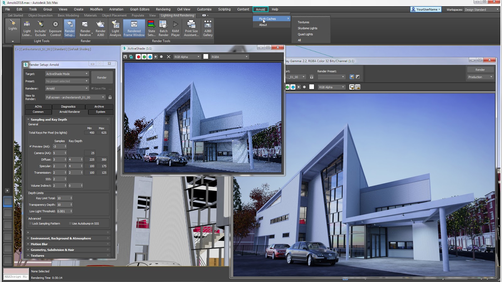
Civil View appears as a drop-down menu item in the Autodesk 3ds Max Design menu bar. The Civil 3D model data is imported from this menu and the Civil View Explorer panel is launched from this menu. The Civil View Explorer panel acts as a primary focal point for the tools that are accessible via Civil View. In the Explorer, all of the scene objects may be accessed. The right-click menu is contextsensitive to the objects and displays the available options for the selected object type. The primary purpose of this panel is:
- To provide a near instant snapshot of the scene contents at particular moments
- To provide access to almost every Civil View command through a combination of contextsensitive rollouts and right-click menus
The Key Civil Visualization Steps The civil visualization process can be divided into five key steps:
- Transfer of AutoCAD Civil 3D data to Autodesk 3ds Max Design
- Adding further 3D content to the scene using Civil View
- Lighting the scene in Autodesk 3ds Max Design
- Rendering in Autodesk 3ds Max Design
- Incorporating Civil 3D based design changes into the visualization with Civil View
Learn more about our other softwares on our latest blogs!


